← All products

SINGLE-PHASE / DC–AC / INDUSTRIAL

MGR-HZF
Series

Industrial SCR solid state relays. Six housing platforms for maximum rated load currents from 40 A to 1000 A.

MGR-H industrial family · DC control / AC output · zero-cross switching
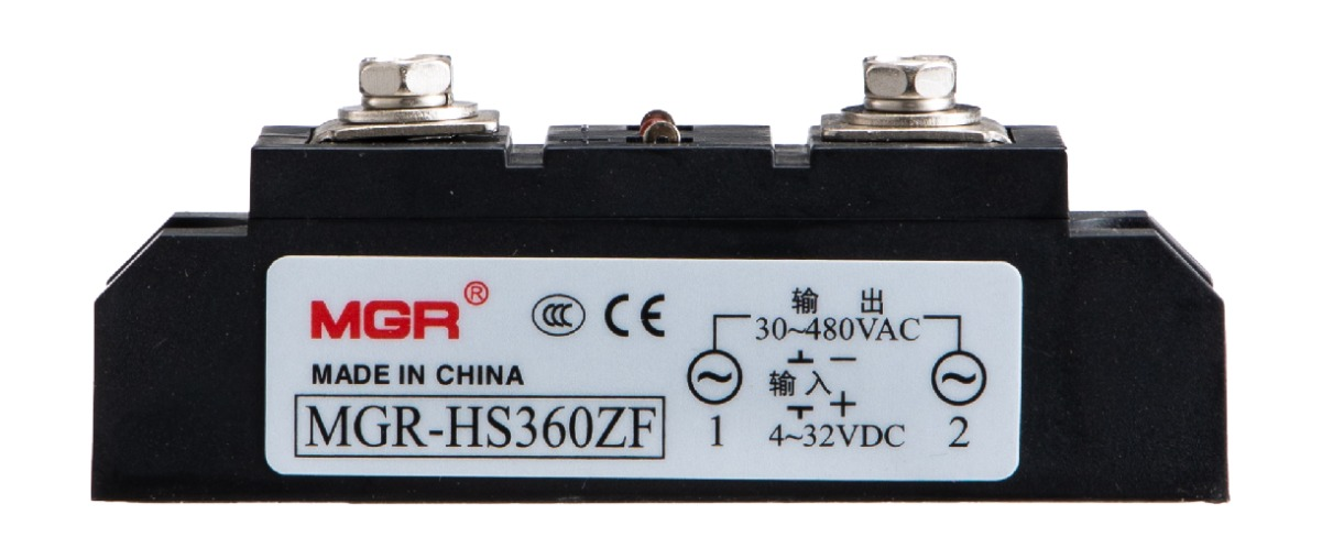
MGR-HS360ZF front view on white background
MGR-HS360ZF · Frame A
MODEL SELECTION

Match current and housing.

400 A is available in two different housings: MGR-H3400Z (Frame C) and MGR-H3400ZD (Frame D). Check both current rating and mechanical dimensions when selecting a model.

FRAME A / 40–125 A

Frame A

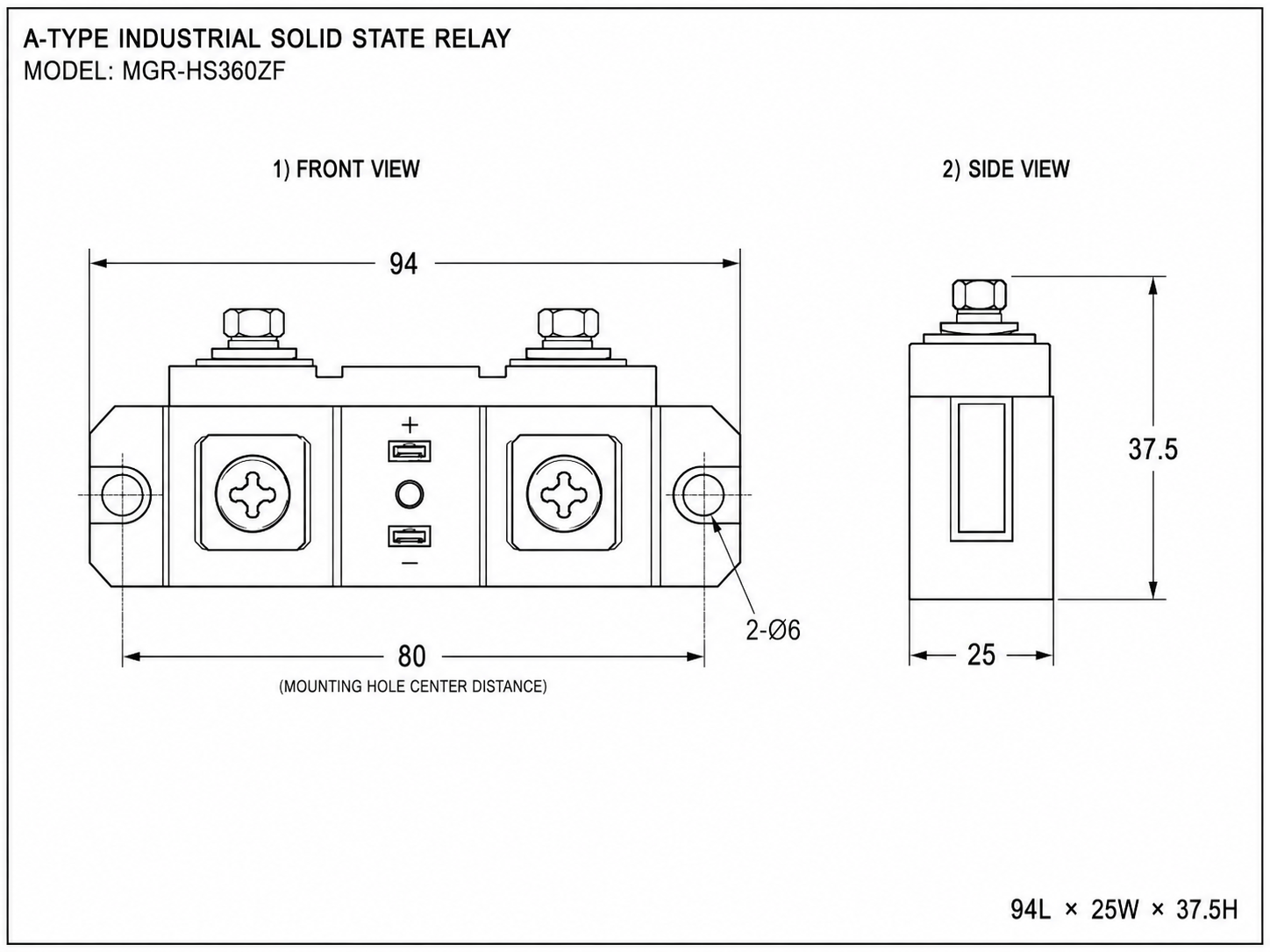
94 × 25 × 37.5 mm · maximum rated load currents below.
MGR-HS360ZF Frame A industrial solid state relay
MGR-HS360ZF · Frame A representative product
MGR-HS340ZFMAX RATED LOAD CURRENT40 A
MGR-HS360ZFMAX RATED LOAD CURRENT60 A
MGR-HS380ZFMAX RATED LOAD CURRENT80 A
MGR-H3100ZMAX RATED LOAD CURRENT100 A
MGR-H3125ZMAX RATED LOAD CURRENT125 A
Frame A mechanical drawing
94 × 25 × 37.5 mm · Click to view the full-size drawing.
FRAME B / 150–350 A

Frame B

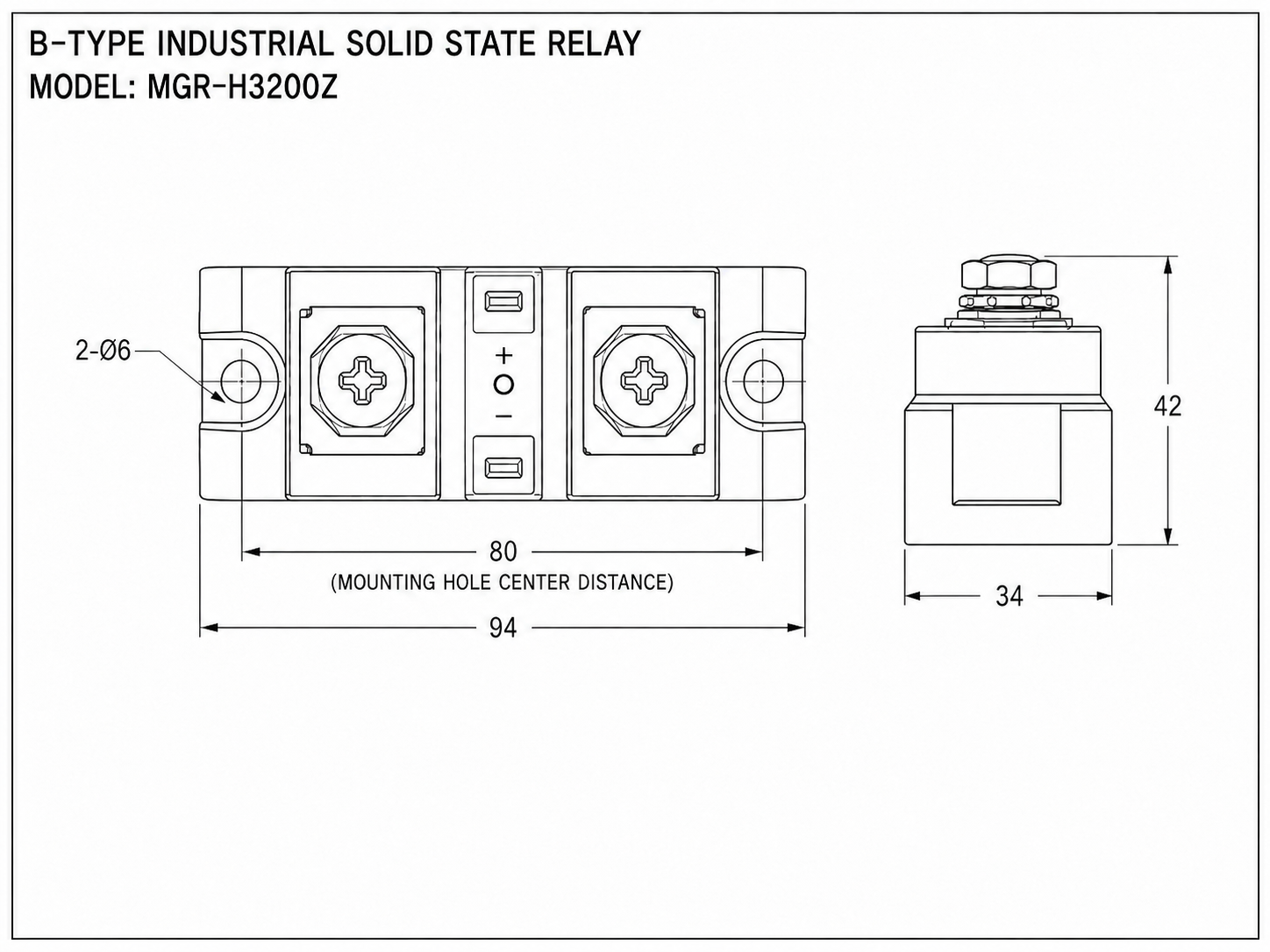
94 × 34 × 42 mm · maximum rated load currents below.
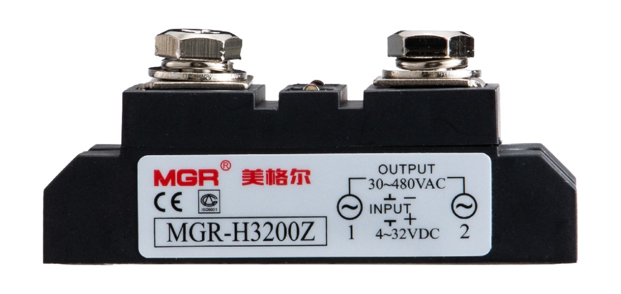
MGR-H3200Z Frame B industrial solid state relay
MGR-H3200Z · Frame B representative product
MGR-H3150ZMAX RATED LOAD CURRENT150 A
MGR-H3200ZMAX RATED LOAD CURRENT200 A
MGR-H3250ZMAX RATED LOAD CURRENT250 A
MGR-H3300ZMAX RATED LOAD CURRENT300 A
MGR-H3350ZMAX RATED LOAD CURRENT350 A
Frame B mechanical drawing
94 × 34 × 42 mm · Click to view the full-size drawing.
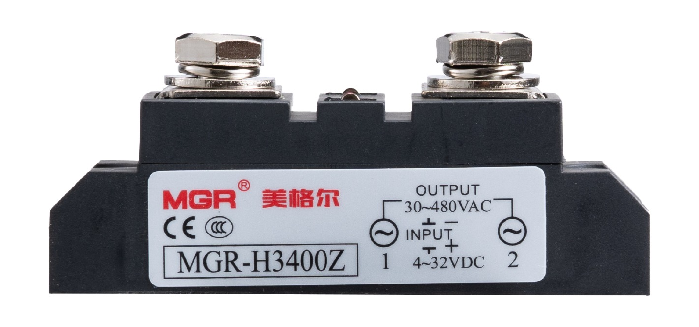
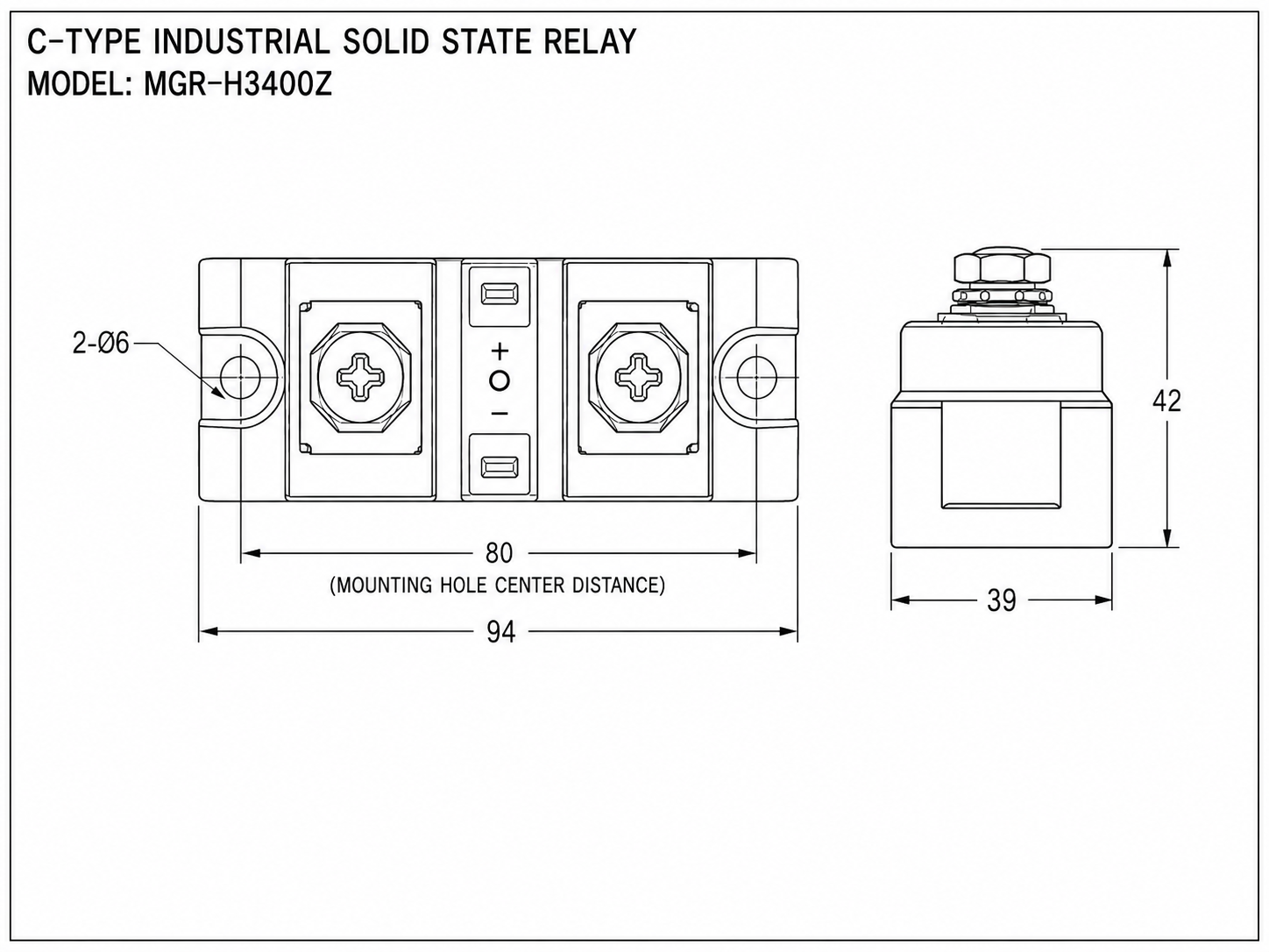
FRAME C / 400 A

Frame C

94 × 39 × 42 mm · maximum rated load currents below.
MGR-H3400Z Frame C industrial solid state relay
MGR-H3400Z · Frame C representative product
MGR-H3400ZMAX RATED LOAD CURRENT400 A
Frame C mechanical drawing
94 × 39 × 42 mm · Click to view the full-size drawing.
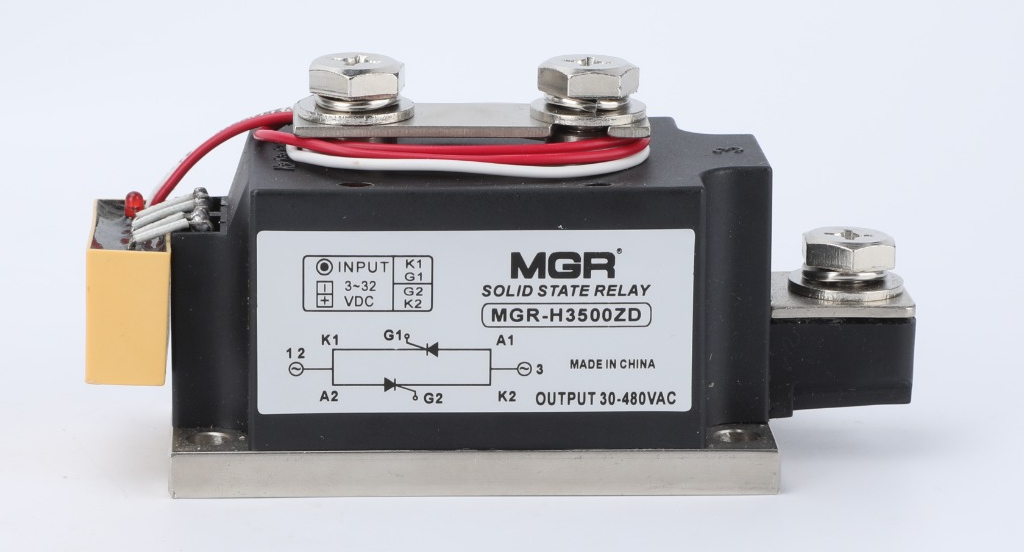
FRAME D / 400–500 A

Frame D

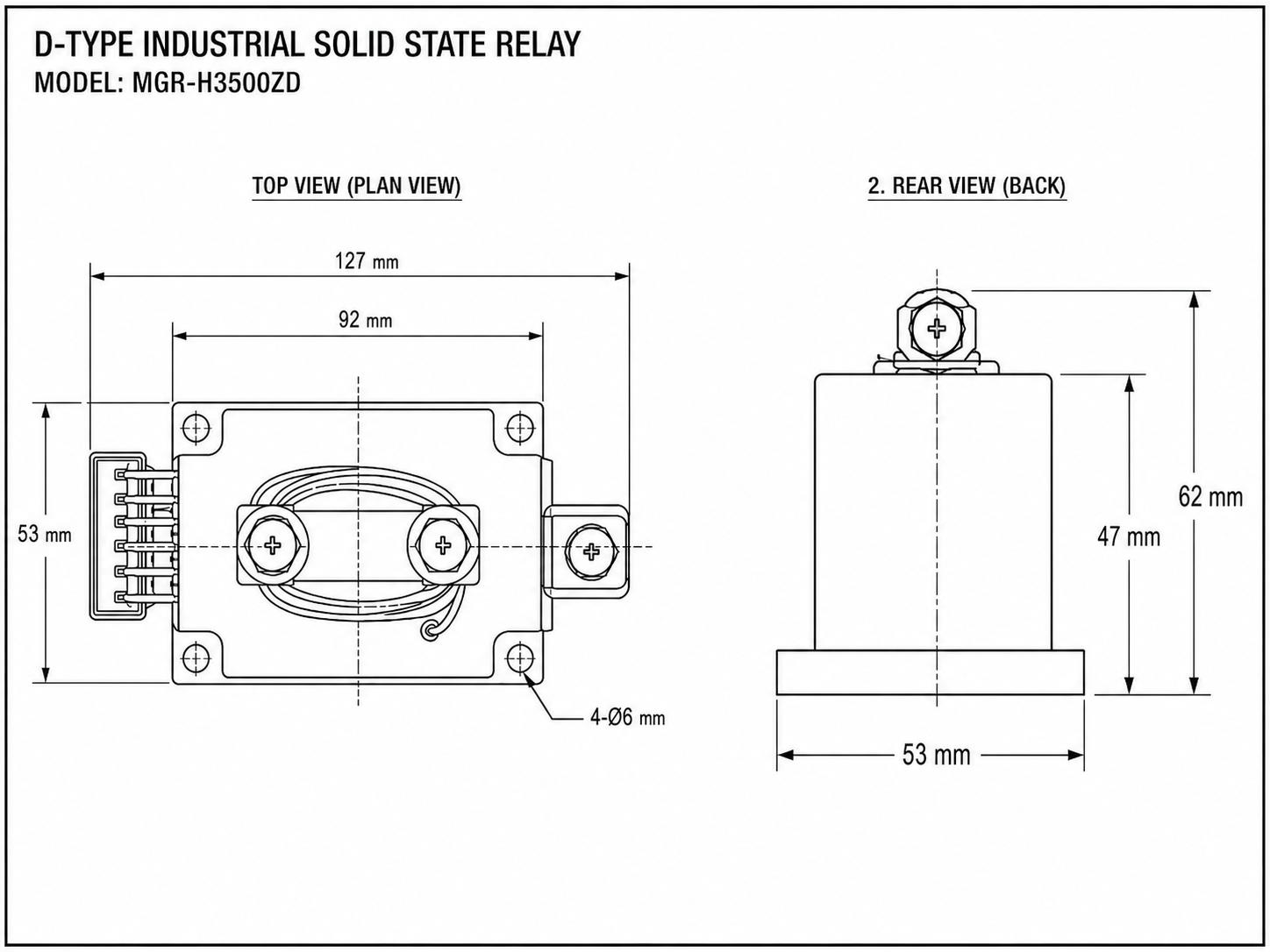
127 × 53 × 62 mm · maximum rated load currents below.
MGR-H3500ZD Frame D industrial solid state relay
MGR-H3500ZD · Frame D representative product
MGR-H3400ZDMAX RATED LOAD CURRENT400 A
MGR-H3500ZDMAX RATED LOAD CURRENT500 A
Frame D mechanical drawing
127 × 53 × 62 mm · Click to view the full-size drawing.
FRAME E / 600–800 A

Frame E

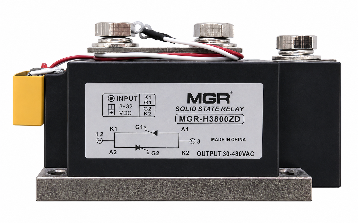
137 × 63 × 68.5 mm · maximum rated load currents below.
MGR-H3800ZD Frame E industrial solid state relay
MGR-H3800ZD · Frame E representative product
MGR-H3600ZDMAX RATED LOAD CURRENT600 A
MGR-H3700ZDMAX RATED LOAD CURRENT700 A
MGR-H3800ZDMAX RATED LOAD CURRENT800 A
Frame E dimensions: length 137 mm, width 63 mm, overall height 68.5 mm, body height 52 mm137 mm63 mm63 mm68.5 mm52 mm
Overall size: 137 × 63 × 68.5 mm (L × W × H) · Body height: 52 mm · Frame E · 600–800 A
FRAME F / 900–1000 A

Frame F

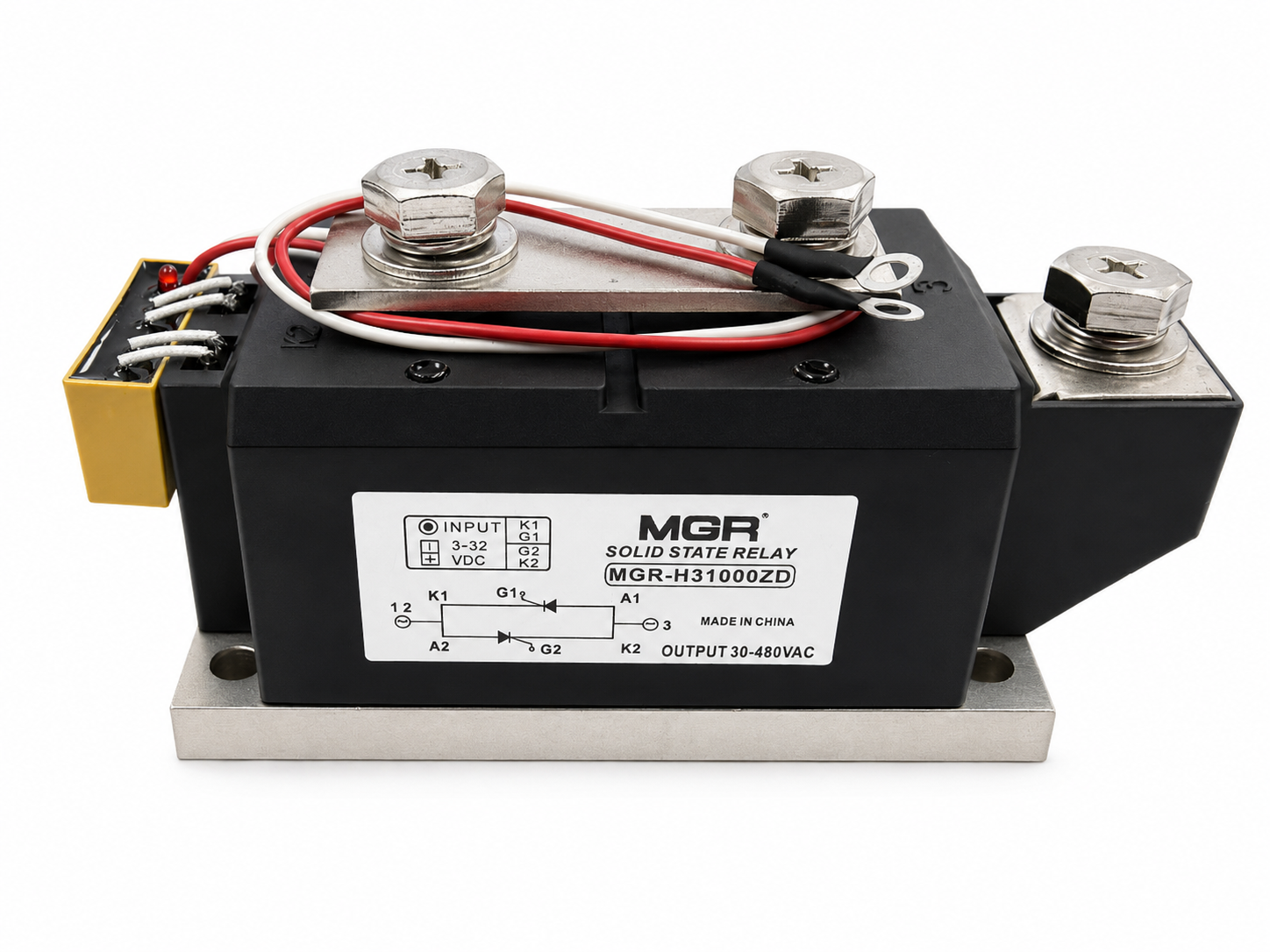
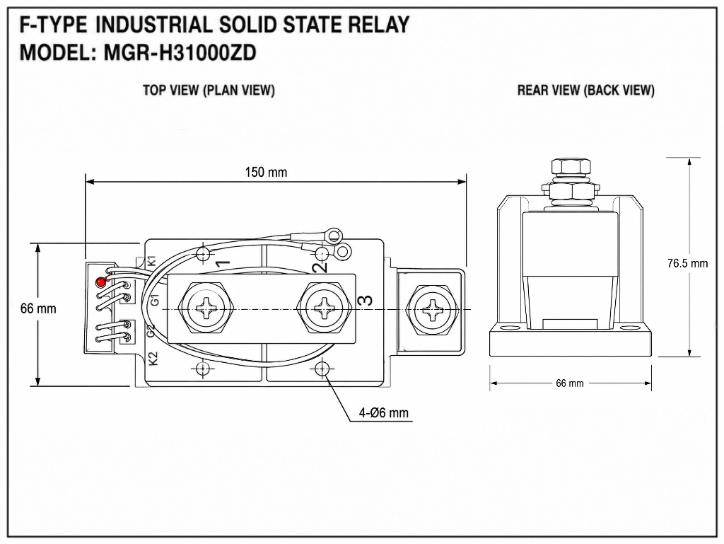
150 × 66 × 76.5 mm · maximum rated load currents below.
MGR-H31000ZD Frame F industrial solid state relay
MGR-H31000ZD · Frame F representative product
MGR-H3900ZDMAX RATED LOAD CURRENT900 A
MGR-H31000ZDMAX RATED LOAD CURRENT1000 A
Frame F mechanical drawing
150 × 66 × 76.5 mm · Click to view the full-size drawing.
ELECTRICAL PARAMETERS

Industrial DC–AC switching.

Control voltage4–32 V DC
Turn-off voltage≤ 2 V DC
Control current≤ 10 mA
Load voltage30–480 V AC
OutputAnti-parallel SCR
SwitchingZero-cross (Z)
Frequency50/60 Hz
On-state voltage drop< 1.5 V
Off-state leakage current≤ 3 mA
RC snubber / input indicatorBuilt-in / LED
Dielectric strength> 3000 V AC
Operating temperature−20°C to +70°C

Use a suitable heat sink and apply thermal grease evenly between the metal base and heat sink. Select appropriate over-voltage protection for inductive loads.

MGR-HZF / CONNECTION

Separate the command.
Switch the AC load.

The series PDF specifies 4–32 V DC control and 30–480 V AC load voltage. The load and relay output form a series circuit. Observe + and − at the control connector. The drawing follows the supplied front view: the large left and right studs are the AC load terminals; the two small centre terminals are vertically arranged, with + above and − below. The centre circle is the indicator.
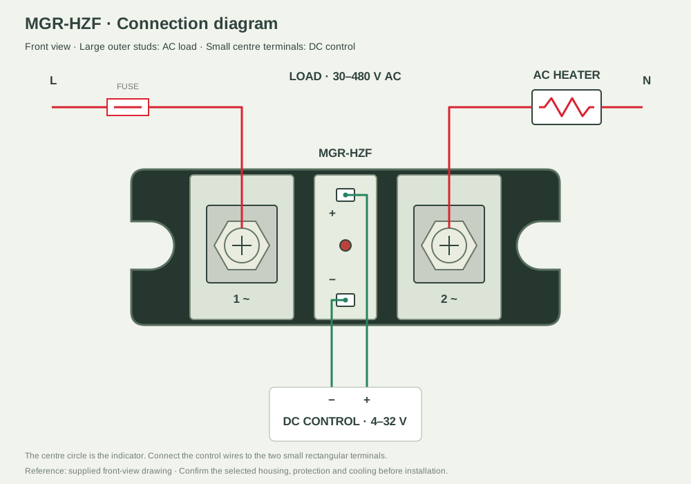
MGR-HZF connection illustration
Select to view full size. Reference example; confirm the supplied model and ratings.

For an inductive load, follow the PDF guidance for a varistor across the output terminals and confirm its rating for the actual circuit.

View reference PDF ↗
MGR-HZF / PRINCIPLE

Wait for zero.
Switch the load.

The Z version uses zero-cross triggering with anti-parallel SCRs. After a DC ON command, conduction begins near an AC voltage zero. After an OFF command, an SCR ceases conduction when load current falls to zero. This is on/off switching, not phase-angle regulation.
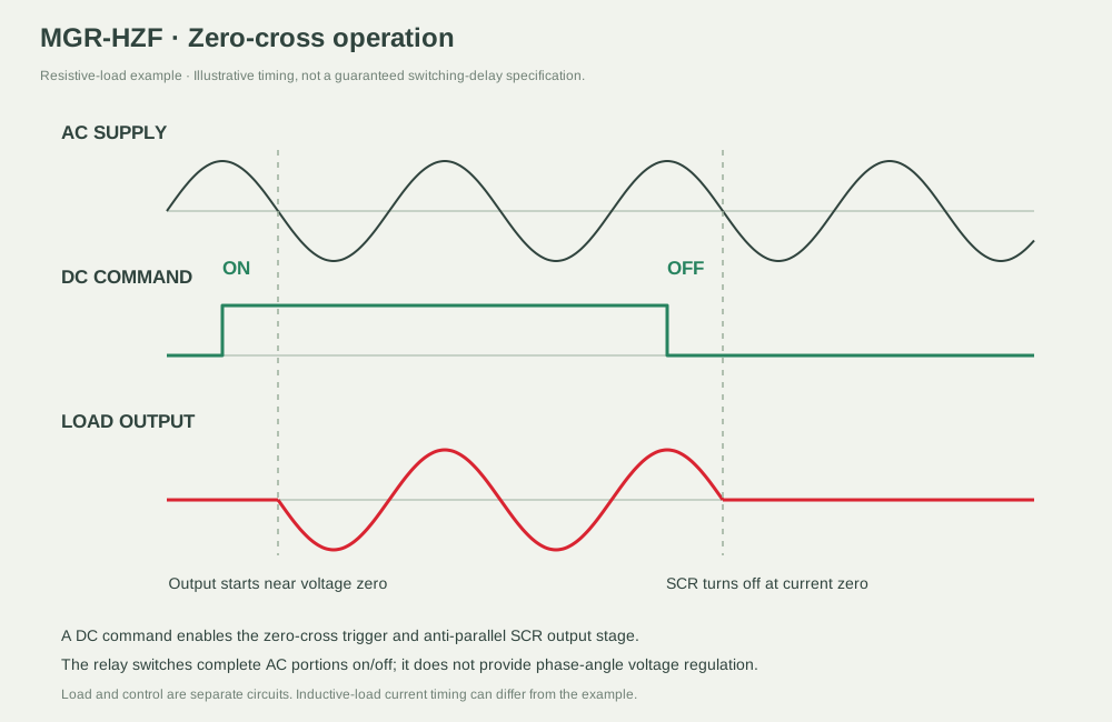
MGR-HZF principle illustration
Select to view full size. Reference example; confirm the supplied model and ratings.
MGR-HZF / APPLICATION

Industrial heater control.

A temperature controller commands the industrial SSR in a process-heating cabinet. The PDF requires a heat sink at 10 A and air- or water-cooled heat dissipation at 40 A and above. Confirm the actual thermal design for the selected model.
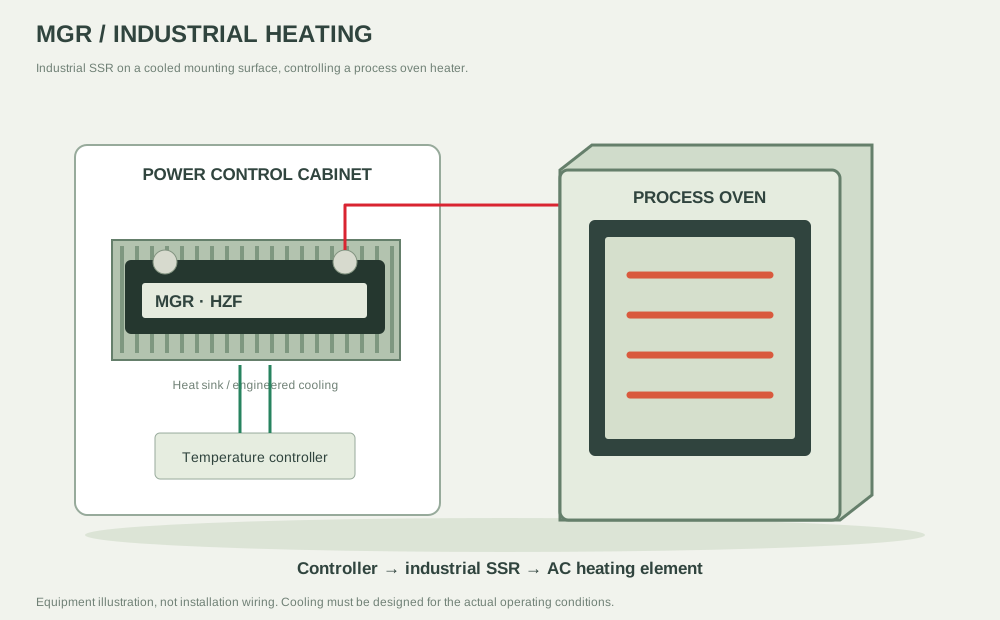
MGR-HZF application illustration
Select to view full size. Reference example; confirm the supplied model and ratings.

Find the right industrial relay.

sales@mgrssr.com ↗